Part 1, Identify the signals
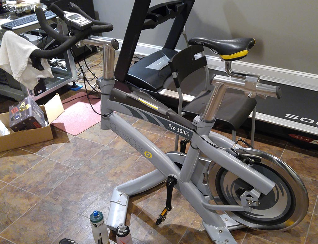
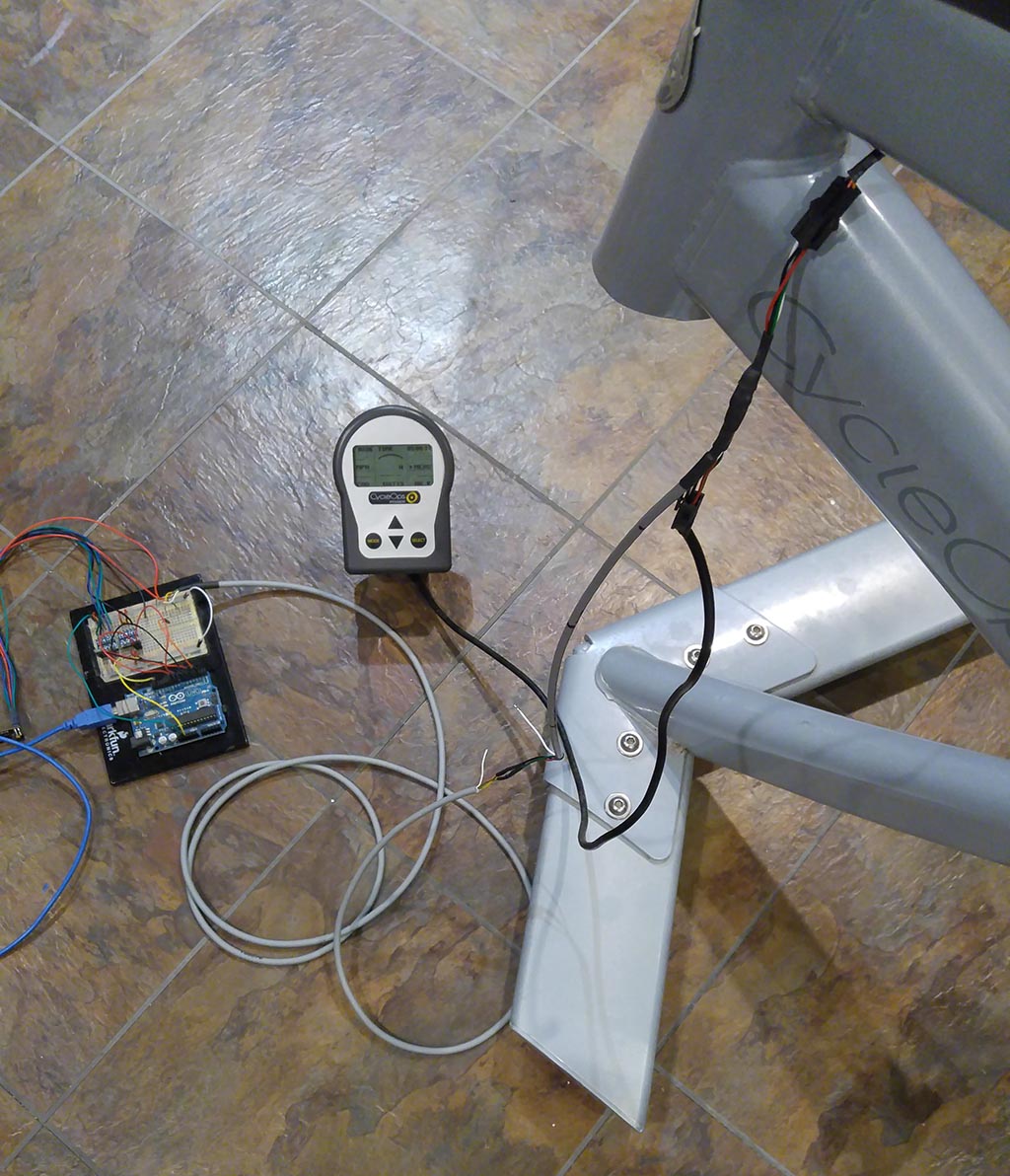
After getting the bike and cleaning it up I started to follow each wire though the bike to identify what plugs into where. Overall the wiring is really simple. The hub of the freewheel in the back has all of the processing electronics inside of it and 2 AA batteries.
I do want to say how useful and downright interesting FCC documents are when first looking at unknown commercial hardware. FCC ID T8P-SL2P402 . They also have some great photos of the internals of the torque tube. From the FCC report we can find out that the hub is using 2.4GHz (same as ANT+ but this isn’t ANT+) but most likely back when this was build in 2007 they hadn’t yet figured out how to get the transmission power needed to get the range while keeping power consumption to reasonable levels (totally my guess). So they went with the approach of putting a receive very close to the hub to relay the data back to the head unit. My guess is this exact same protocol was used on the early wired PowerTap hubs.
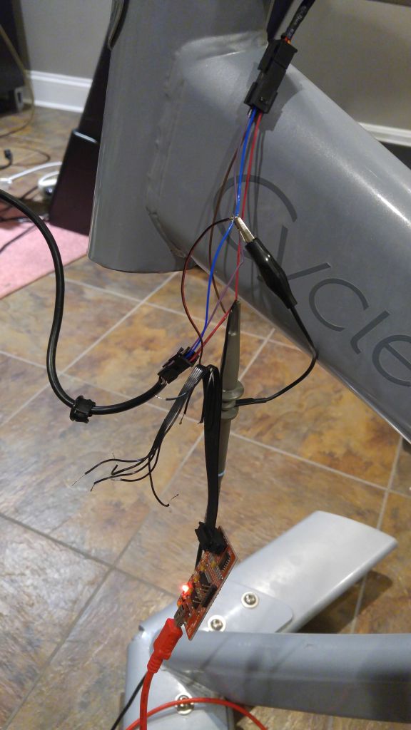
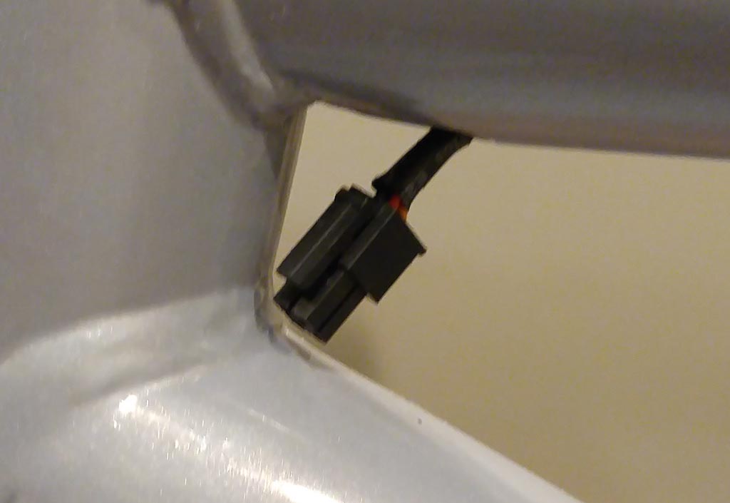
Thankfully the connector used between the computer and the cable that runs to the rear pickup is a very common Molex Micro-Fit. I made a pass though cable that allowed for easy access to all the pins while keeping the rear pickup connected to the head unit
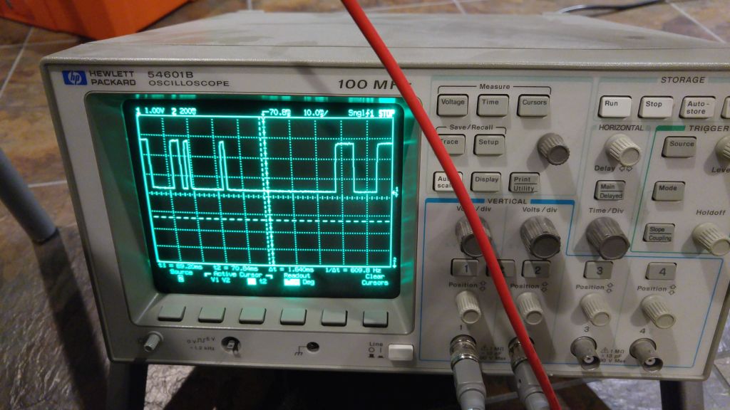
Some poking around with the Oscilloscope and I had the pinout figured out
| Pin | Function | Wire Color |
|---|---|---|
| 1 | 2.95V | Green |
| 2 | Data | White |
| 3 | Nothing | Black |
| 4 | GND | Red |
Let the fun begin, out comes the Logic Analyzer
I’ve done enough work with digital circuits and your run of the mill digital communication protocols to have some idea what to look for but this was my first time going in with no idea and no documentation to turn to for reference. The first 2 days was spent just watching as I applied force to the crank without turning, then letting the cranks spin with no force applied just to see how the signal changed.

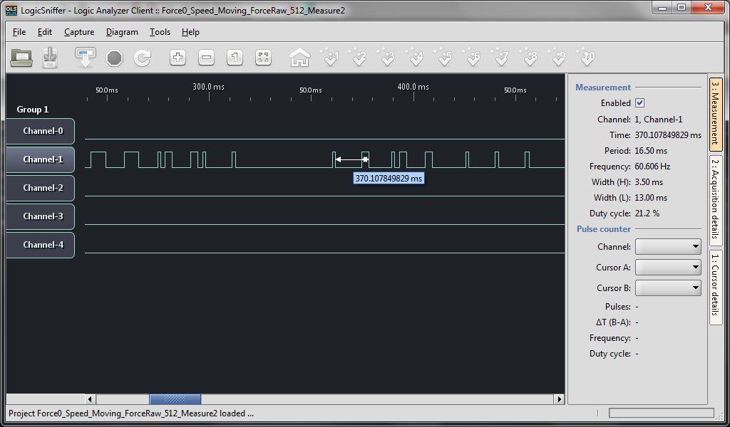
A packet would be sent every 1.043sec
I started by thinking it was just your run of the mill asynchronous serial. I found the shortest pulse in any given chain 1.535ms and assumed (1/0.001535) = 651.4, call it 650baud rate. After trying this and other with every combination of data bit, stop bit and start bit I quickly came to the conclusion this was not right. There really were no start or stop bits.
I know that the torque and speed data must be sent with each packet as both would be displayed on the stock head unit and I could see how the bits shifted depending on if only torque or only speed was applied
The great discovery was that the starting pattern told me everything.
- 4 bits of data in 7.249ms = 1.812ms per bit (The code uses 1.770)
- 6 bits of 0s in 9.152ms = 1.525ms per bit (The code uses 1.545)
- Repeat
Once I had this variable bit rate figured out the rest just fell into place
I doubt the method I came up with is the most elegant way to work with this data but it worked for me.