CycleOps Pro300 PT to ANT+, Part 7, V1 is back with better software

I’ve received several requests for updates on the V2 hardware. I’ve had a breadboard version of the V2 sitting on my desk for months. I haven’t yet found the advantages of the ESP8266 processor enticing enough to make new PCBs and deal with the new headaches that will come with trying to get everything working as well as it was on the ATmega32U4.

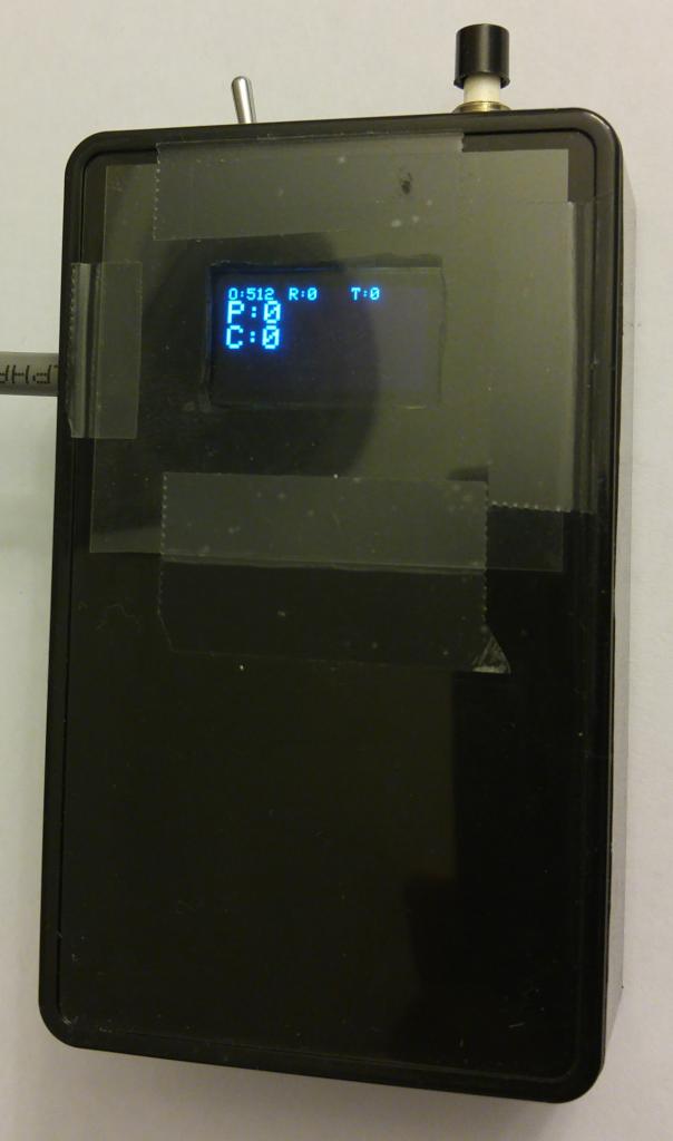
Back to the development on the ATmega32U4, I went off to find a solution to the memory issues. The power meter conversion code is relatively small, the majority of the space was being consummed by the library for the OLED display, while very nice to have it isn’t really needed for the device to function. At the time I was using Adafruit_SSD1306 an excellent library that includes test and image support. For what I was going, text only was just fine. Hunting around GitHub and Google I found the very well designed SSD1306Ascii. While not a drop in replacement for the previous library do the conversion over took me a few hours and memory usage went from close to 90% where I was dealing with random reboot and odd issues to a much more comfortable 44% of program memory being used. Solution found, time to move on to the next issues.

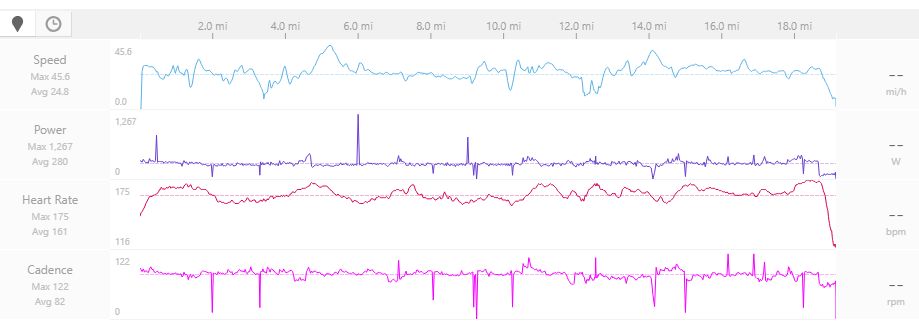
I prefer to bike outside whenever the weather allows but with December here on the East Coast of the US mother nature doesn’t always allow for that. I’ve been using the CycleOps bike with Zwift just about every day and have started to see random spikes of both power and cadence on my plots. This was unacceptable.

I wish I could put out 1000+ watts

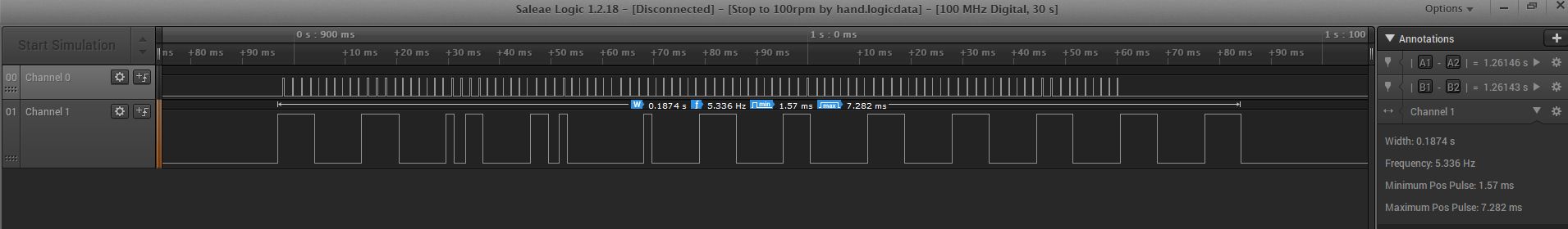
Near the beginning of this project I purchased a Saleae Logic 8 logic analyzer. This has turned out to be one of the most valuable tools in my collection of electronic debugging. For a data packet with no noise we can see that the shortest time for any single bit of data is 1.57ms. Any time a bit is less that this we know that must be an error bit

Data Packet with no errors

Looking for when a high signal is <1ms I was able to find a packet with a glitch.

Data Packet with glitch that was causing spikes

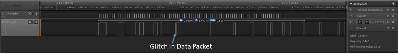
Now that the glitch had been identified I was able to write code to check if a data bit was being read while a glitch occurred. If this happened the code will not update power or torque and will wait for the next data packet. The disadvange of this is that power and torque will be updated at a 2 second interval when a glitch is detected rather than the standard 1 second of each packet. This was a minor price to pay for power and cadence data that is spike free. All of these changes can be found in the GIT Repository CycleOpsPro300PTtoANTPlus

CycleOps Pro300 PT to ANT+, Part 4, Hand Wired Prototype

I’ve received a few requests for a step by step tutorial on how to build the circuit that I had talked about below. Sorry, this post won’t be that step by step guide but it will provide many of the tools. As a mid stop on my way to making a robust design others can copy I built a battery powered, hand wired, point to point monster that I could keep connected to the bike for my own personal winter training. At the same time I drew up the electrical schematic and laid out a PCB that would make it easy for others to build at home without doing painful point to point wiring. I had a few requirements for the finial design.

  1. Li-Ion Battery Powered
  2. Built in USB Charger for the battery
  3. Built in display to show, Torque, Power, Cadence and some parameters for debugging such as the current torque zero offset
  4. USB programmable for firmware updates and general messing with it at a later time without needing to use an In-Circuit Serial Programming (ICSP).

Battery: I’ve have a pile of 14500, 900mAh 3.7V Li-ion batteries laying around that fit perfectly in the corner of the project box. I’ve been using the bike about an hour a day for the last month and have yet to need to charge it. One of these days I’ll measure the power draw to get a rough idea of how long it should last. This first prototype has no ability to charge the battery. I’ll have to use one of my external chargers to do it for now

Display: I chose to use a small 128×64 OLED display that I had been playing around with. It has incredible view-ability, draws very little power and will run off 3.3V without any external components. It also has really easy to use libraries that made getting the data on the screen very quick to add to the code.

The hand wired unit I built does not have a built in charger but that is addressed in the final PCB design.

Just as before, the PCB design files and source code can be found in Github CycleOpsPro300PTtoANTPlus. SeeedStudio the PCB vendor I used has a minimum 5 board order so if there is any interest leave a comment below and I’m happy to send the extra to a good home $5 a board.

For anything following along at home the ANT+ module I had previously used doesn’t look to be available anymore. I found one that looks to be exactly the same NRF24AP2 Networking Module / 8-channel / Serial Interface / ANT Networking. This will be the unit I test with the PCB version of the design.

Photos of of the hand wired box and the PCB layout

Copyright blinkyme 2023
Tech Nerd theme designed by Siteturner