This post will be a tutorial to building your own CycleOps Pro300PT to ANT+ Adapter. For anyone who may have purchased one of these bikes many years ago and finds it sitting unused in a corner this is a great way to bring new life to your bike for use with Zwift, Golden Cheetah or any other ANT+ compatiable application. If you bike looks like the photo below and came with the computer shown below, this tutorial is for you.

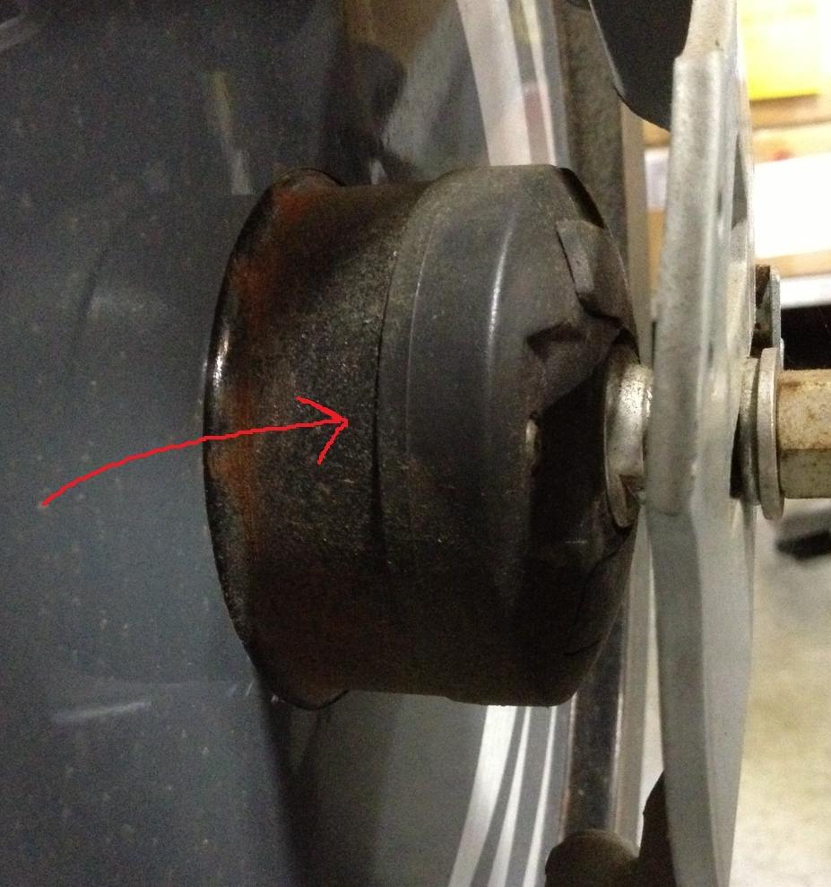
The version I have has the power meter welded to the fly wheel so there is no chance to have Cycleops upgrade the hub. If you happen to have the style that is bolted to the flywheel Cycleops will upgrade the Power Cartridge (part 18849) for $339. This wasn’t an option for me as I have the welded style hub shown on the right
Disclaimer:
This post assumes you have basic electronics knowledge including
- Soldering of wires, though hole and 0603 SMT components to a PCB,
- Don’t worry if you don’t, this is a great project to learn on as the PCB has large spacing and is very forgiving in part misplacement.
- Programming an Arduino, specificly the Pro Micro, see Pro Micro & Fio V3 Hookup Guide
- Downloading code from GIT hub. All the code, CAD models and PCB files are kept at GitHub Repository
- Buying parts from electronic suppliers such as Mouser or Digikey
Some great tutorials can be found on Sparkfun and Adafruit
Parts Required:
- The complete parts list in excel format can be downloaded from the GIT here
- Molex Micro-Fit, 4 Circuit Plug Housing and Pins
- A few of the parts are non-standard mouser parts and needed to be ordered from ebay or AliExpress these included
- PCB – I am happy to sell some of my extra, just put a comment below otherwise the gerbers are in the GIT if you want to make your own boards
- NRF24AP2 Networking Module
- Arduino Pro Micro, Ebay or Sparkfun. Just make sure to get the 3.3V version
- Project Box, Ebay
- Optional OLED Display, Ebay
- Battery 14500 3.7V Li-Ion, DX or Amazon or Ebay
Full Parts List for those who just want to skim without going to GIT
| Part | Value | Package | Description | Mouser Part # | Link | Device |
|---|---|---|---|---|---|---|
| C1 | 4.7uF | 0603-CAP | Capacitor | 581-06036D475MAT4A | CAP0603-CAP | |
| C2 | 1.0uF | 0603-CAP | Capacitor | 581-06036D105MAT2A | CAP0603-CAP | |
| C3 | 2.2uF | 0603-CAP | Capacitor | 581-06036D225MAT2A | CAP0603-CAP | |
| C4 | 1.0uF | 0603-CAP | Capacitor | 581-06036D105MAT2A | CAP0603-CAP | |
| C5 | 1.0uF | 0603-CAP | Capacitor | 581-06036D105MAT2A | CAP0603-CAP | |
| D1 | RED | LED-0603 | LEDs | 645-598-8010-107F | LED0603 | |
| D2 | BAT20J | SOD-323 | Schottky diodes in SFE's production catalog | 511-BAT20JFILM | DIODE-SCHOTTKY-BAT20J | |
| D3 | GREEN | LED-0603 | LEDs | 645-598-8070-107F | LED0603 | |
| Q1 | 2.5A/30V | SOT23-3 | Generic PMOSFET | 621-DMG2307L-7 | MOSFET-PCHANNELDMG2307L | |
| R1 | 2.49K | 0603-RES | Resistor | 660-RK73H1JTTD2491F | RESISTOR0603-RES | |
| R2 | 10.0K | 0603-RES | Resistor | 660-RK73H1JTTD1002F | RESISTOR0603-RES | |
| R3 | 200 | 0603-RES | Resistor | 660-RK73H1JTTD2000F | RESISTOR0603-RES | |
| R4 | 200 | 0603-RES | Resistor | 660-RK73H1JTTD2000F | RESISTOR0603-RES | |
| R5 | 470 | 0603-RES | Resistor | 660-RK73H1JTTD4700F | RESISTOR0603-RES | |
| R6 | 10K | 0603-RES | Resistor | 660-RK73H1JTTD1002F | RESISTOR0603-RES | |
| R7 | 1.43M | 0603-RES | Resistor | 71-CRCW06031M43FKEA | RESISTOR0603-RES | |
| R8 | 1.0M | 0603-RES | Resistor | 652-CR0603FX-1004ELF | RESISTOR0603-RES | |
| R9 | 10K | 0603-RES | Resistor | 660-RK73H1JTTD1002F | RESISTOR0603-RES | |
| R10 | 470 | 0603-RES | Resistor | 660-RK73H1JTTD4700F | RESISTOR0603-RES | |
| R11 | 4.7M | 0603-RES | Resistor | 660-RK73B1JTTDD475J | RESISTOR0603-RES | |
| R12 | 4.7K | 0603-RES | Resistor | 667-ERJ-3GEYJ472V | RESISTOR0603-RES | |
| R13 | 4.7K | 0603-RES | Resistor | 667-ERJ-3GEYJ472V | RESISTOR0603-RES | |
| U$1 | NRF24AP2 | NRF24AP2 Networking Module | Aliexpress | F10644_NRF24AP2 | ||
| U$2 | 53375-02 | 53375-02 | 2.50MM 2P VERT HDR FRCTN POS LOCK | 538-53375-0210 | 53375-02 | |
| U1 | MCP73831 | SOT23-5 | Charge management controller | 579-MCP73831T-2ACIOT | MCP73831 | |
| U2 | AP2112K-3.3V | SOT23-5 | Voltage Regulator LDO | 621-AP2112K-3.3TRG1 | V_REG_LDOSMD | |
| U4 | TPS78223DDCR | SOT95P280X110-5N | Low-Dropout Linear Regulator | 595-TPS78223DDCR | TPS78223DDCR | |
| B1 | PRO MICRO | SPARKFUN_PRO_MICRO | SparkFun Pro Micro | Ebay | SPARKFUN_PRO_MICRO | |
| Power Switch | Mountain Switch | Toggle Switches SPST OFF-ON | 108-0041-EVX | 108-0041-EVX | ||
| Reset Switch | Mountain Switch | Pushbutton Switches METAL BODY BLK | 103-1013-EVX | 103-1013-EVX | ||
| Project Case | Ebay | |||||
| OLED Display | Ebay |
Build Instructions
Prepare the Cable
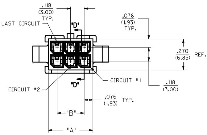
I’m going to take a guess and say for most people this is going to be the most challenging part. I happen to have access to the proper crimping tools for working with Molex Micro-Fit connectors at work. For most, you have 2 options. Cut the existing cable off of your wired head unit or using some needle noise pliers and solder do your best to crimp the pin onto the wire. I have used the pliers and solder method for years for a non-mission critical application like this you should have no problem. I’m following the pin out numbering as used on the Molex Data Sheet for the 43020-0400 4 pin housing, The image below shows a 6 pin, we will be using a 4 pin version. Don’t forget the heat shrink to keep things nice and clean. The completed end can be see below.
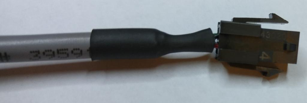
Going off of the colors of the wire I happened to have on hand, wire the connector as follows, substitute the color of wires you use as needed. I didn’t find any function for Pin 3 but I happened to be using 4 wire cable so just to keep things clean I connected all of the pins. You will see later that this pin goes to nothing at the PCB side. I am also using shielded cable. This is not necessary at all but at the PCB side I was able to solder the shield directly to the PCB to help strain relief the data, ground and signal solder joints
| Pin | Function | Wire Color |
|---|---|---|
| 1 | 2.95V | Green |
| 2 | Data | White |
| 3 | Nothing | Black |
| 4 | GND | Red |
Solder the Components
Time to take out the solder iron and the 0.015″ solder or some solder paste and hot air and get soldering. The layout of the board puts almost all of the SMT components on the back with lots of room to place them with tweezers and even enough room to hand solder them if you prefer. I suggest doing all of the SMT parts first then the through hole components after the SMT. Last solder all of the wired switches and data line. I put a small rubber grommet on the line that runs to the bike to give it a clean look when going though the project box. You will notice a large pad just above the connection for the bike data line. I used a cable with a shield. While this pad is grounded and in theory will help protect the wires from radiated noise my primary reason was to use the shield as strain relief for the wire. I didn’t want to solder directly to the OLED display to make it easy to remove the cover and work on the PCB if needed at a later date. I found a Molex 0022162040 to be the perfect fit to the pins and provide a nice right angle pin to solder the wire to. You can see this is the right most picture, its the white connector.


Prepare the Case
The case I used for this project was brought on Ebay Electronic Project Box/ Enclosure Instrument Case. A few modification are required for mounting of the power switch, 0 force calibration button, OLED display and access to the USB port. The location and size of the holes can be taken from the CAD model. The OLED Display was attached to the cover with hot glue at the 4 corners. I then put a sheet of transparency plastic on the outside to protect the OLED from the inevitable sweat that will fall on on it. I held the plastic on with some scotch magic tape but really need to find a cleaner solution.


Program Arduino
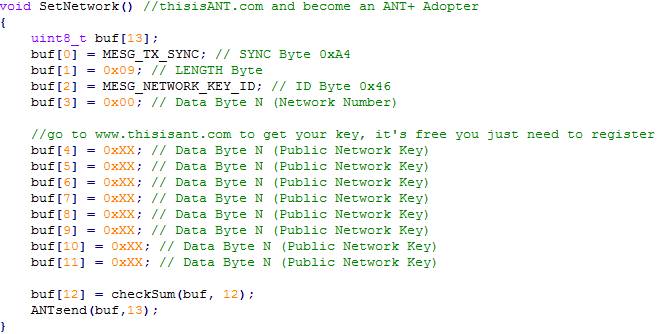
Before programming there is 1 small modification that must be done to the code. I am not able to provide the ANT+ network key with the code. Getting one is free and quick
- Go to https://www.thisisant.com/
- Create a free account
- After you are logged in go to https://www.thisisant.com/developer/ant-plus/ant-plus-basics/network-keys
- Find the line “The ANT+ network key is 8 hex values and is shown below”
- You will find 8 hexadecimal number, put each of the 8 numbers in order into this section of the code, replacing the XX with the numbers you are provided
 Follow the instruction on Sparkfun for setting up the Arudino Pro Micro Pro Micro & Fio V3 Hookup Guide
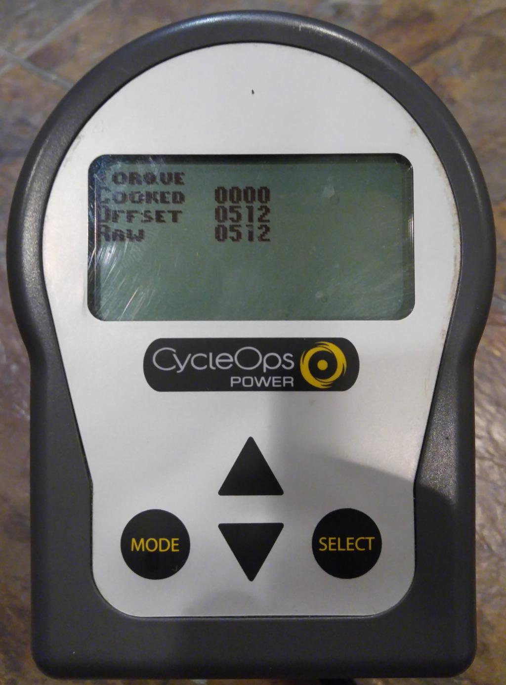
Upload the code and apply power, on power up, even if not connected to the bike the OLED display should look like this.
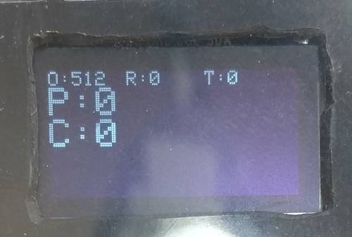
By default I have the following items displayed on the screen
- O: Torque (counts)
- R: Torque (counts)
- T: Torque (in-lbs)
- P: Power (Watts)
- C: Cadence (RPM)
Selling extra parts
If anyone is interested I have 4 extra PCBs that I would like to sell for $5 each, PayPal would be ideal method of payment. If interested let me know in the comments below and I’ll get in touch.
I’m interested in a circuit board. Please email me info.
Matt, I believe I have the same model CycleOps Pro300PT as you described. I have a wire from a sensor near what appears to be a welded hub, up to the computer. I have a software engineering background that included circuit boards but most of that work was done about 30 years ago. In 2014, CycleOps did offer a flywheel+hub replacement for this bike for $800 which included Ant+ support (although in the recent reading maybe it was incomplete Ant+). Anyway, I contacted them recently to see if I could get that hub and they said parts were no longer available…which is when I turned to google and found your response on http://darrencope.com/2015/01/21/recording-power-from-cycleops-300-pro-indoor-bikes/ and the detailed instructions here. Wonderful detective work on your part across software and hardware.
I see you offered to sell an extra PCB to posting comments. I’m wondering if you’d be willing to create the whole solution (for the lazy types like me), charge a fair price for your labor and parts, such that I could plug in your solution (preferably inline with the existing Joule head), and also have it broadcast Ant+? I have a Wahoo RFLT+ on my road bike which acts as an Ant+ receiver and can broadcast in BLE to an iPhone. My ultimate goal is to use this solid CycleOps bike to get into things like Zwift or otherwise. Let me know.
Hi,
Great work! This project is beyond me but exactly what I need. Would you be interested in making 1 (or 2 actually) on a commission. I would compensate you generously.
Walter
Do you have any on the PCBs left? I would like to get 2.
Walter
I am also interested to acquire 1 or 2 of the PCBs if you still have any spares.
Hi Matt, I’m interested in one of your PCBs if available or to have you make the same thing for me that you did for yourself. Happy to pay you for it.
thanks, Larry
Very interesting. A couple of questions –
With the Cycleops hub upgrade you mention (which I assume is included with the Pro 400 indoor bike which transmits some sort of private ANT stream), how would this project be changed? Would it be possible to implement the “ANT receive/ANT+ send” code using a single PC? Maybe ANT+ dongles do not work in transmit mode, so the additional hardware would still be required?
I have a Pro 400 bike which does work with Rouvy and Zwift, but not with, for example, Zwift on Apple TV because there is (seemingly) no way to get from the ANT stream being sent to the BLE stream required. If an ANT+ stream were available through a bridge like this, then one of the currently available ANT+ to BLE converting devices (Cable, for example) might do the trick..
Thanks for any suggestions.
K.Riegel,
As far as I know all USB ANT+ dongles support bi-directional communication. Anself USB ANT+ is a personal favorite of mine, great performance at a reasonable price. I have never looked at a CycleOPS Pro 400 so I don’t know exactly how they implemented the resistance control commands. Apple seems to have something against ANT+ and everything I have read says it just will not work on Appple TV. If Cycleops is using ANT+ FE-C as there method of communication for both power and resistance a product such as CABLE may work.
I’m curious, does the resistance control from Zwift work with your Pro 400 or do you just get power and cadence and have to do manual resistance control?
I have a side project to implement the ANT+ FE-C protocol on this existing hardware GITHUB ANTPlus_Arduino. I have the bi-directional communication working and have just started on the hardware design to add software controlled resistance to a 300PT bike. More to come later on this.
Great writeup.
Im interested in a pcb if you have any left, let me know.
Hi Matt:
I’m interested to proceed and willing to do the soldering myself. Do you still have an extra board I can buy to get started? Also super interested in the ANT+ FE-C protocol for the older wired 300PT. Please keep me posted on your hardware ideas. Are you thinking of a servo-motor to turn the handlebar twist-knob cable tensioner?
Sadly I’m out of PCBs for now. However, the design and Gerbers for the V1 design are published in the GIT repository if you want to order them before V2 is ready. I’m working on a new design (V2) that should improve the ANT+ performance and allow for future expandability including support of FE-C. I have a few different ideas for how to implement the resistance control. That seems like a good topic for my next post (It’s been too long).
Hi Matt: Fantastic information! Have you complete design on V2? If not, I’ll take a stab at making V1, but it will stretch my skills in every way – I would love to buy a completed version from you with fair compensation for your time(?).
Mark,
I’m putting together an update right now. I’ve ditched the V2 design in favor of improvements to the code for the V1 hardware. I’ve been able to solve the memory problems and have also added several new features that protect against bad data packets that get sent from the receiver near the rear hub. If you were going to build a V1 unit, I’ll suggest you start. I will be continuing to develop the software and can help you along the way if you run into any issues.
Very interesting post!
I have a later Cycleops 300 which does transmit ANT+ but cannot be controlled by Zwift – resistance is changed via me twisting the manual knob when to need to hammer a virtual hill or whatever.
I have thought about getting a better (smarter) trainer set-up, but I just love the physical stability of the Cycleops frame — so much more secure and solid feeling compared to any actual bike on indoor trainer.
Very curious about the idea to add a servo-motor to control the brake-resistance shoe – with an interface to FE-C – wow – would be the best of all worlds!
Anyone ever verify this on 400 pro?
I don’t have a 400 pro to validate this with but I would be very curious if given the chance to work with one. I don’t have any details on how the computer of the 400 pro connects to the variable resistance drive.
Matt,
This is brilliant – thanks for the hard work. I’ve already ordered parts to put my own together. Any recommendations on where to get boards made?
Hi, I’m from France. I use a 400 PRO with Rouvy.
All is functionnal : Power, Cadence and Speed readings. Power setpoint is also provided by rouvy. All controlled on my smartphone.
If I need more resistance, Just put on “Plus” button like if I was shifting on a regular bike…
So it seems PRO 400 use ANT+ proprietary channel to control the brake unit…
But decoding this with regular Hardware (Smarphone with BT /ANT+) could be achieved : Rouvy only did it…
(Source on this Zwift post : https://forums.zwift.com/t/even-after-trying-all-work-arounds-unable-to-pair-with-cycleops-400-pro/5595).
What I would like to to is using my 400 PRO directly with my Garmin Edge 530… Unfortunately, nothing is recognized by the Edge (Power sensor, Cadence/Speed, or brake unit), Even in the Home trainer section.
Maybe Saris / Cycleops may ask Garmin money to provide protocol / keys to transceive these data… Or just Garmin don’t care about very few old trainer users !
Best way would be to transceive proprietary ANT+ communication from CycleOps and broadcast it on regular ANT+ channel / Protocol as any other trainer… Simple Theory, complex to do without CycleOps/Saris cooperation.
Hi Matt
Many thanks for your post on this, I have an old PT300 languishing, unused due to conectivity issues and am keen to try to make it work. I have lots of time during lockdown!!
Do you have any more of the circuit boards? I’m not sure I could make the board up myself.
Many thanks
Adam
adam
Hi Matt,
Thank you so much for all the hard work you put into this! Also, thank you for your assistance in trouble shooting my issues!
To anyone else interested I have some extra PCBs, an extra screen, and some other miscellaneous parts. Shoot me an email if you’re interested: tregas11[at]gmail.com
Thanks,
Tim
Happy to help and so glade it all worked out. Enjoy indoor winter biking with power.
Matt; You are genius. The solution is super cool and glad you were keen to share the instructions. I am wondering about the port on the side of the Cyclops computer that can connect to USB cable and go right into a PC. Is it not possible to get all of the signals from that USB cable and condition the signals to “look” like something Zwift could recognize ?
Just wondering if you tried that as a possible hack.
At the very beginning I looked at this path. I spent a day or two looking to see if a real time stream was available over the USB port. While I can’t say I exhausted all options I didn’t see any real time stream data available over the USB port. From what I could see the USB port was only used to download saved rides. At some point I had a copy of CycleOps PowerLink software installed to see if it could stream data, it could not. At that point I moved on to what turned into the current solution.
I need to know how to change the battery for the power tab on the cyclops pro 300 PT thanks
matt, do you know a good way to make sure we have the correct wires connected correctly in the back?
Our kids were messing around and caused a disconnection near the rear tire and now I’m not sure what color needs to connect to which wire if I solder them. Any chance you know or have ideas on how to figure this out?
Sorry, I finally (after almost 10 years) sold my PT300 bike and replaced it with a newer smart trainer. So I don’t have my bike to reference anymore. You can check if the colors are the same on both sides of the connector. Assuming CycleOps used the same colors on both sides, you can match to the other end.
This is stellar work. I recently came into a bike with the original cycle ops Powertap hub. Listening with my hackRF it looks like it’s still alive. from what little i can find it looks like this unit uses ANT (not ant+) to send data to a receiver mounted within 7 inches of the hub, then a wire runs to the bike computer. I can’t find this receiver, nor computer then I ran across your work. I’d like to build a relay module to receive the signal then rebroadcast it as ant+. I see the NRF24AP2 is a transceiver. Do you think it has enough gusto to receive the old signal and rebroadcast as ant+, or should I get two NRF24AP2 chips, one for receive one for broadcast? What would be your general approach here?
Hi Dan, Thanks for finding this project.
Given my personal skill set, I would take the approach of using 2 CPUs, one to handle ANT+ receive / transmit and a 2nd to handle Input / Output and in the case of this project the display. In my case being highly power efficient wasn’t high on my priority list but being able to leverage the massive Arduino library code base made this project possible. I’m far from an expert on the NRF24AP2 and would say it likely would be possible to merge all of this function into a single CPU. This project was completed prior to the AI/LLM explosion. I’ve found in more recent projects LLMs can be a great tool for helping to combine functions such as this into 1 application and might be worth looking at.